Preamble
There are two Areva Evolutionary Pressure-Water Reactors (EPRs) under construction at Hinkley Point in Somerset and two more are planned for Sizewell in Suffolk.
The Emergency Core Cooling System (ECCS) of a pressurised water reactor (PWR) is the main line of defence against a radiation accident which could result in severe casualties and lead to the contamination of a huge area of land, possibly covering tens of square kilometres.
The UK has one PWR, viz., Sizewell B built by Westinghouse, which in its Technology Systems Manual Section 5.2, states that an ECCS provides core cooling to minimise fuel damage following a Loss-of-Cooling Accident (LOCA).
Similarly, in compliance with the US Nuclear Regulatory Commission's code, an ECCS has to provide core cooling under loss of coolant accident (LOCA) conditions to limit fuel cladding damage by limiting the rise in temperature of the fuel cladding to 1204°C.
Licensees have constructed pilot plant evaluation models to show that with a range of LOCA severities and core heat situations the ECCS complies with this requirement, (See NRC 10 CFR Appendix K to Part 50 - ECCS Evaluation Models for seven basic parameters to be considered).
If just the reduction in core damage is the desired outcome from the activation of an ECCS, it does not assume that the reactor can be restored to operation after a deployment. There was never such an expectation.
The following thermodynamic analysis based on the published technical descriptions of the EPRs shows conclusively that the described emergency core cooling systems, if needed, will not suffice to allow operation to be restored and shows that in this regard, the EPR ECCS can't work.
Major incidents leading to core meltdowns
Several major accidents or incidents have taken place since civil nuclear power was first introduced in the 1950s, but two examples are highlighted for examination, viz., Three Mile Island 2 in the US and Fukushima Daiichi in Japan.
At PWR Three Mile Island 2 in Harrisburg in Pennsylvania in the USA in 1979 a loss of feed water to the steam generators' secondary side, led to an operator led depressurisation of the reactor cooling system (RCS), performed excessively by a stuck-open pressuriser relief valve, resulting in the partial melting of its core from the reduction in interstitial cooling.
Delayed and confused warnings to the public from the authorities about the ongoing crisis at the plant led to a disorderly, attempted evacuation by about 140,000 people. Three Mile Island gained notoriety as the main highways leading away from Harrisburg became jammed with cars as residents attempted to flee.
At Fukushima Daiichi in Japan in 2011 three operational Boiling Water Reactors (BWRs) and one shut down BWR in the nuclear island suffered a station blackout (SBO) from an offshore earthquake. The three in-operation reactors were shut down by the application of their control rods prior to the tsunami in response to the earthquake causing it, which cut off the connection to the electricity grid. Also a short time later, a consequent tsunami flooded the basement where the standby generators were located.
The batteries supplying emergency lighting in the control room and its instrumentation soon ran out, as did the controls of steam turbines driving emergency coolant pumps which might otherwise have dealt with the residual heat following the shutdown. The expiration of the batteries caused the loss of the steam-driven turbine coolant pumps of Units 2 & 3, terminating the removal of the decay heat. The control room was plunged in darkness, alleviated eventually with a string of car batteries.
The findings of the investigating teams are well known, but the progression of events leading to the destruction of Unit 1's building by an hydrogen explosion and the melting of its core requires further examination. Following the SBO, unrelieved by standby generation, there was a build-up in pressure caused by the lack of cooling to remove the remaining residual heat in the shutdown reactors.
A separate article, "Fukushima Review 2021", examines the possibility that the lack of standby power and the batteries led to the progressive withdrawal of the control rods, progressively uncovering the fuel cans, leading to the rise in the system pressure, the hydrogen explosions, a possible steam explosion in Unit 3 and the melting of the cores.
To avoid the rupture of the torus wetwell, over-pressured by steam from the reactor vessel (RV) relief valves, operators opened automatic relief valves manually to depressurise the torus through the exhaust stack. This led to an hydrogen explosion, which destroyed the service floor above it, while the depressurisation led to the melting of the core, with the melt possibly going through the base of the RV. The destruction of all four reactors and their buildings followed.
The condition of the former nuclear island remains fraught.
Units
Current units cited in this article:-
Pressure MPa megapascal 1 MPa = 145.038 psig (15.5 MPa is equivalent to 155 bar or 2,248 psig ).
Energy MWth megawatt thermal or MWe megawatt electricity
The Evolutionary Pressure-Water Reactor (EPR)
Pressure water reactors now predominate the nuclear power sector, but there is only one operational in the UK, Sizewell B. The twin Areva Evolutionary Pressure-Water Reactors (EPR) under construction at Hinkley Point (HPC) are further PWRs, while two more PWRs are planned at Sizewell (SZC).
Water at atmospheric pressure boils at around 100°C, so to be used for raising steam to drive a turbo-generator it has to be heated under pressure. The EPR uses nuclear fission to heat water to 328°C to produce steam at 311°C in steam generators (SGs). This means that the pressure in the reactor vessel has to be held at more than the saturation pressure of water at 328°C of 12.5 MPa to avoid boiling and with a margin of 3 MPa, runs at 15.5 MPa.
Otherwise, below this saturation pressure of 12.5 MPa the hot water in the reactor vessel will "flash" to form small bubbles of steam, producing a water/steam mix with a rapidly increasing volume. While, with a continuing depressurisation to below 8 MPa, the saturation pressure of the returning coolant from the SGs at 296°C, the whole contents of the coolant system will have flashed to a steam/water mix.
Steels are weakened at high temperatures, so the reactor vessel body is made of a massive carbon steel forging to withstand a high pressure with a stainless steel liner, deployed because the inside is subject to attack from an aggressive boric acid in solution.
The EPR reactor vessel (RV) is at the limits of design (17.6 MPa) with a diameter of 5 m, a height of 13 m and a removable head requiring massive, bolted flanges to avoid their rotation and gasket leaking. The RV body has eight nozzles to connect it by pipework to the four pumps between it and the four steam generators (SGs).
The head is also constructed of an outer thick, carbon steel shell with a stainless steel liner, while the penetrations for the 89 branches to mount the 89 control rod drive mechanisms (CRDMs) have Alloy 690 tubing inserts. The inserts are driven in drilled holes to give an interference fit and are welded inside to the liner. Previously, the use of Alloy 600 (Inconel) in some cases succumbed to cracking, but some still remains in older, working PWRs.
Sizewell B has 2 steam-turbine driven auxiliary feed water pumps, but the EPR has not.
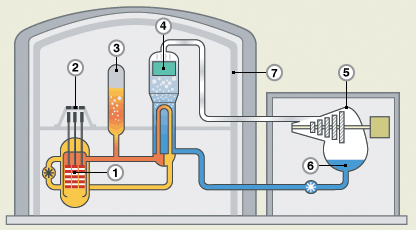
The Areva EPR components
Figure 1
EPR simplified flow diagram
In this EPR diagram, the core (1) is
shown in orange, the control rod drive mechanisms (CRDMs) (2) are shown in
black, the four pump cooling circuit
is in light brown and yellow as with the pressure controlling pressuriser (3). The feed water is shown in blue,
the steam is shown colourless in one of the four steam generators (4), in one of
the two turbines
(5) and the condensate/feed water in its condenser (6) is shown in blue.
The heat is 4,500 MWth thermal to produce 1,600 MWe electricity. The residual 7% residual heat is initially 315 MWth, before decaying. Located on the coast, the waste 2,900 MWth is discarded, by circulating seawater.
Reactor vessel
The critical part is the reactor vessel (RV), designed to contain the core and its control rods. The control rods containing boron for neutron absorbance are moved up and down between the fuel cans to regulate the amount of fission and the resulting heat. In the EPR they drop down to shut down the reactor.
The EPR reactor core has 241 fuel assemblies, each assembly has 265 fuel rods, the total number of which is 63,865. The active length of a fuel rod is 4.2 m.
There are 89 control rod drive mechanisms (CRDMs) raising and dropping 89 control rod assemblies, each with 24 rods, i.e., 2,136 rods.
The internal diameter of the RV is 4.885 m, but with a core of 62,865 fuel rods in cans and 2136 control rods, the cooling water passages through narrow interstices.
When operating, the EPR reactor vessel contains water at a high pressure of 15.5 Mpa, a leaving "hot leg" temperature of 328°C and a returning "cold leg" temperature of 296°C. With lowering pressures the high pressure hot water flashes to a water/steam mix and to steam.
As well as a coolant, the water acts as a moderator, slowing the speed of the escaping neutrons, providing more collisions and fission.
Steam
Generators, coolant pumps
The EPR has four steam generators (SGs) with the radioactive coolant circulating through tubing to separate it from the steam to the turbines. There are four coolant pumps circulating the coolant from four hot legs though the tubes in the steam generators to the four cold legs. The main coolant lines connecting the SGs and the pumps to the eight entries to the reactor vessel have an internal diameter of 780 mm.
The pressuriser's (PZR) role is to maintain the pressure of the coolant circuit inside prescribed limits. The water in the lower part has electrical immersion heaters to trim its temperature and a spray system at the top to condense steam.
The reactor cooling system (RCS) has a capacity of 445 m^3.
Coolant flow
The coolant removes 4,500 MWth from the core with a total flow of 113,360 m^3/h driven by 4 pumps of 9,000 kW each, totalling 3.6 MW of drive power. There are 63,865 fuel rods in cans with, in between them, 2,136 neutron absorbent control rods plus temperature and level gauges and an aeroball system for neutron flux measurement in the core. This leaves just small interstices for the flow up through the 4.2m of core height.
The nuclear fuel core provides up to 4,500 MWth, which is an intensive amount of heat in what is a relatively small space. This means that when a PWR is operational the coolant flow through the RV, the pipework, the pumps and the steam generators has to be maintained absolutely or the fuel and its enclosing cans will rise in temperature and the core will melt.
Shutting down
Control rods contain boron able to absorb neutrons so that the nuclear fission taking place in the core can be reduced by inserting the rods, increased by removing them slightly or stopped almost completely by fully inserting them.
The control rod (CRDM) housings have a unified pressure with the RV allowing them to drop under gravity into the core interstices, giving a fast shutdown. The action leaves a declining core residual heat, starting at 7% of the full heat.
When the reactor is shut down and with the control rods dropped in place there is initially a residual heat of 7% of the full (315 MWth), decaying rapidly, but still requiring a flow of coolant to avoid a partial core meltdown.
Station Blackout
A station blackout (SBO) can be caused by a disconnection from the grid followed by the consequent shutdown of a reactor with its loss of load. Or, by an internal electrical fault in the station. An SBO can be avoided if at least one of the standby generators starts up automatically within a short period. The station batteries maintaining the reactor controls may not last until some power is restored. The loss of the reactor controls can be severe, as in Fukushima.
If just one of the four primary coolant pumps shuts down, the reactor trips. At full heat the flow from all four pumps is needed. The pumps have flywheels to motor down in a station blackout (SBO), giving time for the reactor to be shut down by the dropping of the control rods by gravity as the CRDM housings' internal pressure is unified with that of the reactor vessel.
The standby generators will then be required to power the residual heat pumps (LHSIs).
Core meltdown
As described above, a reactor core providing up to 4,500 MWth is an intensive source of heat in what is a relatively small space, requiring a constant flow of cooling water to dissipate it. If this flow of coolant is reduced or interrupted the fuel and its enclosing cans will rise in temperature and melt. This means that when a PWR is operational the coolant flow through the RV, the pipework, the pumps and the steam generators has to be maintained absolutely or the core will melt.
After the reactor is shut down and with the control rods dropped in place there is initially a residual heat of 7% of the full (315 MWth), decaying rapidly, but still requiring a flow of coolant to avoid a full or partial core meltdown. An abrupt loss of coolant at full power (4,500 MWth) would produce a full core meltdown, probably melting through the base of the RV and with the molten core, then flowing into the spreading area below the RV.
ECCSs
Emergency core cooling systems (ECCSs) are conceived to prevent a core meltdown if the coolant flow fails. Evaluation models tested in pilot plants claimed to show that the rise in cladding temperature was kept below 1204°C to limit core damage. They will feature in the two nuclear power plants under construction and the two more proposed in the UK, being of the EdF Evolutionary Pressure-Water Reactor (EPR). There is a similar ECCS (SIS) in Sizewell B.
The ECCS concept is to inject water
(some from a pressurised accumulator, borated to absorb neutrons and reduce fission) into the
reactor vessel cooling circuit to cool the core after the normal coolant flow fails.
ECCSs are thought to be needed in the event of a component failure, a loss of
coolant accident (LOCA) and
for a station blackout (SBO). However, without recourse to standby power
generators the safety injection pumps will not be powered.
ECCSs were available at Three Mile Island and Fukushima, but failed to be deployed, for different reasons, to prevent the cores to melt.
It is the purpose of this analysis to show that, with all but a minor loss of cooling accident (LOCA), the associated EPR Emergency Core Cooling System (ECCS) is unable to prevent a partial core melting or, in the case of a severe LOCA, occurring under full power, it will be a catastrophe with fuller core melting.
The EPR ECCS
The EPR ECCS combines a Safety Injection System (SIS) with a Residual Heat Removal System (RHRS) in a dual function.
During normal fuel change, after the reactor is shut down, the residual heat has to be removed and the steam in the secondary SG-turbine-condenser circuit "dumped" by cooling in the condenser for return to feed water or vented to atmosphere.
The SI/RHR system consists of
4 Low Head Safety Injection (LHSI) pumps (2.1 MPa) with 4 Residual Heat Removal (RHR) heat exchangers to perform two functions, viz., compensating for loss of coolant "when the primary pressure is sufficiently low" (sic) and also the residual heat removal.
4 Medium Head Safety Injection (MHSI) pumps (9.2 MPa).
4 Accumulators with borated water for neutron absorbing are kept under pressure (4.5 MPa) and will operate automatically through non-return valves into the cold legs once the coolant system circuit pressure drops significantly below the accumulator pressure.
The EPR ECCS operation
Presumably the loss of pressure caused by a Loss of Cooling Accident (LOCA) will trigger an automatic response by the control system to drop the control rods and shut the reaction down to its residual heat, while simultaneously starting the MHSI pumps and opening the valves for the supply of coolant. Even if some, or all, of the four MHSI pumps providing 9.2 MPa head have been started by the control system, or manually by the operators, the injection of coolant into the system cannot proceed until the system pressure has reduced beyond say 8 MPa.
The four accumulators are maintained at 4.5 MPa pressure. The mechanised response to a LOCA is that, after the pressure in the coolant system has sufficiently reduced, non-return valves will open so that the contents of the accumulators can be released into it. But that cannot proceed until sufficient of the coolant has been lost in the break to reduce the system pressure to below 4 MPa so that there is a differential pressure to open the non-return valves.
The water in the accumulators is borated, i.e., it contains derivatives of boric acid to provide the neutron absorption of boron as a fission limiter in core interstices, most of which will not have a control rod.
However, during the above two actions, the necessary prior fall in the hot water pressure has flashed most of the water to steam and a water/steam mix will be violently leaving the break. The phenomenon is called "nucleate boiling" followed by "film boiling", reducing the heat transfer rate from the can surfaces to the mix. The un-transferred heat raises the temperature of the fuel and the can surface, the swelling of the cans reduces the cross-section of the interstices, which together with the steam voids in the interstices block the flow of coolant, thus increasing the fuel cladding temperature. When high enough to cause the fuel and can melting the temperature appears to be high enough for an ion exchange with the zirconium in the can alloy and the steam to produce hydrogen.
The operation of the LHSI pumps is possible after the pressure has fallen to less that 2 MPa, by when the system is virtually emptied. So, the role of the LHSI pumps in a LOCA is obscure, as they are normally associated with a heat exchanger to deal with the residual heat as the other duty of the double SIS/RHRS function.
Before the actions of the SIS pumps and the accumulators can proceed, the damage to the core is done by the preceding depressurisation and there may as well be an hydrogen explosion.
Severity of a Loss of Coolant Accident (LOCA)
Small LOCA
In March 2010 Sizewell B suffered a small LOCA from its pressuriser. Some of the immersion heaters located through its base leaked, but the LOCA was so small that any fall in coolant operating pressure was negligible. The leak was detected by a rise in radioactivity in the containment. The reactor was shut down and the leaking immersion heaters replaced.
Design basis LOCA
This considers the severance of one of the RCS 780 mm internal diameter hot or cold legs and features in the computer simulations in which the fuel cladding surface temperature is shown to be held below 1024°C by the operation of the ECCS safety injection system.
Worst case LOCA
Incidents
In Beznau-1 in Switzerland in 1971 and in Davis-Besse in the US in 2002, the ultimate LOCA severity of a breakaway of a CRDM was just avoided when the stress corrosion crack in a penetration branch for the mounting of a CRDM failed to be fully circumferential. In both cases big holes in the carbon steel outer shells of the heads were eaten away by the leaking of boric acid through the cracks.
In the case of Beznau-1, the acid ate a crescent-shaped hole in the carbon steel outer shell round the penetration, ca. 25 mm deep and 45 mm wide. At Davis-Besse the hole extended over a much larger area and being 214 mm deep reached the inner stainless steel liner, which being just 4.8 mm thick cracked, but held the RV pressure. Fortunately, the cracks were in the weld on the inside of heads, below the interference fits of the Alloy 600 penetration tubing which had axial cracks, leading to a slow loss of boric acid solution onto the carbon steel head.
CRDM housing breakaway consequences
If the crack in the penetration is circumferential, the CRDM housing will be severed off and will breakaway. (The breakaway of a CRDM is recognised as a "design basis accident" in the design of a PWR containment building with a floor of modular missile shields above the control rod casing as the pressure inside the CRDM housing launches it like a rocket after a breakaway.)
The suddenly opened penetration in the RV head allows a rapid depressurisation, which "flashes" the high temperature hot water immediately to steam, producing a water/steam mix in the interstices between the fuel cans. A water/steam mix will, with its rapid volume increase, will flow above the core to the open branch and be released into the containment. This will hinder the dropping of the control rods, because the CDRM housings pressure, shared with that in the reactor shell, will be lost and the rods will not fall by gravity.
This will be a LOCA at near full heat. The immediate nucleate boiling in the can interstices will reduce the heat transfer from the fuel to what is then a steam/water mix and the core will melt, while hydrogen will be produced by ion exchange of the steam with the zirconium in the cans' alloy.
In such an incident, producing a rapid depressurisation, the starting of the MHSI pumps will be too late to have an effect, as also will be the entry of the borated water from the accumulators as the non-return valves will not open until the pressure is around a quarter of the RV operating pressure.
With the lowering density of the steam/water mix, the volume of it leaving the core interstices will, in any case, create a barrier to the injected water and will hinder the lowering of the control rod assemblies into the core in order to relieve the full 4,500 MWth heat.
A breakaway of a CRDM housing is therefore a "worst case" LOCA.
Considerations
Perhaps an incident such as a bursting disc fracturing in the pressuriser due to an over-pressure caused by a control fault might be a case where an ECCS would not be required to ameliorate the LOCA. If the control rods were applied rapidly and the residual heat could be relieved by the flow from the LHSI pumps. It would depend on the recognition by the control system, or by the operators, of the reason for the sudden depressurisation and the consequent closure of guard valves to stop it and the start of the LHSI pumps. It would also mean that there would be no station blackout, as power for the controls, pumps and other machinery would have remained active.
But the breakaway of a CRDM would be beyond amelioration and a catastrophe.
The normal quiet routine running of the power plant lulls the operators into complacency and they are unprepared for the denouement. At TMI 2 the mode switches indicated that the stuck relief valve was closed, but it was open, depressurising the coolant system. Meanwhile, the liquid level gauge in the pressuriser showed the core was covered, but that was with the expanded volume of coolant due to its steam content, which provided a poor heat transfer from the fuel cans to the coolant. This resulted in confusion rather than complacency.
Perhaps the controls can be programmed to cover all contingencies, but will the next big event be presaged? When the ECCS is really needed, it will not work.
Core meltdowns
Core meltdowns occurred at Three
Mile Island 2 and Fukushima 1, 2 and 3
At TMI 2 the steam generator feed
pumps stopped working while the standby pumps' valves were under maintenance. The
reactor was shutdown, but the residual decay heat raised the pressure, lifting
the relief valve, which stuck open, then relieving the pressure.
With the instruments in the pressuriser showing a high level of coolant, it was thought that the core was covered. However, its interstices contained a water/steam mix with its poorer heat transfer from the can surfaces. The temperature of the cans and the fuel in them rose with the inadequately relieved residual heat and the core partially melted.
At Fukushima, the earthquake
triggered the shutdown of all three working reactors. The control rods were applied and
the full heat reduced to the residual heat. The
tsunami caused the station blackout by disconnecting the station from the grid
and flooding the standby generators. So although some cooling was applied, it ceased after the
batteries ran out, losing the controls of steam-driven emergency coolant delivery
turbines.
In Unit 1 the pressure rose in the reactor vessel until the relief valves were opened manually by operators. An hydrogen explosion followed Unit 1's depressurisation, destroying the service floor and causing structural damage.
The explosion pressure was held by the containment at TMI 2;
at Fukushima further explosions caused catastrophic damage to all four units.
In the 3 units running, the control rods were
applied in consequence of the earthquake and the reactors shut down. Although only 7% of full power, falling
rapidly in hours, the residual heat was sufficient to raise the RV pressure. The
required depressurisation to avoid the rupturing of the RVs was sufficient to create the
hydrogen explosions and to cause core meltdowns.
The Fukushima Diachi catastrophe involving all four units is well recorded and is not the subject of this analysis. The circumstances of just Unit 1 is cited to show the significance of a depressurisation before full, or residual heat is removed.
A near catastrophe
At Davis-Besse in the US in 2002,
boric acid leaking from a cracked control rod drive mechanism branch in the
reactor vessel head ate a large hole in the steel shell. The pressure was held
just by the stainless steel liner. Had the vessel ruptured at full power (in
comparison with just the potency of the residual heat), the consequences are
unimaginable.
A LOCA in an EPR
So, the most likely LOCA in an EPR is probably the worst. As there are 89 branches on the RV head, crack detection in a fuel change on the top of the head is a difficult task.
Figure 2
Replacement reactor vessel heads under manufacture at Framatone with just 65 CRDM penetrations.
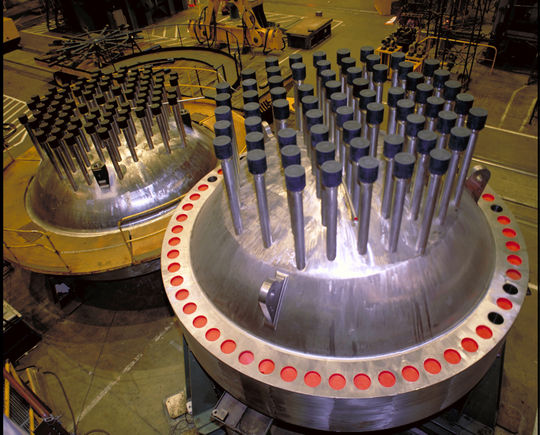
Also in the EPR there are 89 potential CRDM severances with severe LOCA potential. Whether the Alloy 690 in service will prove more sustainable and resistant to stress corrosion cracking than the Alloy 600 in the coming 60 years of operation is yet to be known.
Reactor Vessel Head Inspections
To avoid a CRDM housing breakaway a visual inspection routine is required at every re-fuelling outage and a volumetric surface examination every ten years, as follows.
The entire outer surface of the Reactor Vessel Head is visually examined by remote means every re-fuelling outage to confirm absence of any leakage. White powder traces of boric acid are particularly significant.
Volumetric and surface examinations of the 89 CRDM mounting "penetrations" (flanged branches) are required every ten years. These consist of:-
Eddy current surface examination of the penetration tube bore, which extend beyond the inner surface of the Reactor Vessel Head and well beyond the weld area towards the outer surface ensuring full coverage of the area of concern.
Ultrasonic examination of the surfaces is also undertaken during the same re-fuelling operation.
The frequency of these examinations is in accord with industry practice every ten years.
This follows experience and research relating to Primary Water Stress Corrosion Cracking (PWSCC) associated with Alloy 600 materials. The EPR Reactor Vessel Head utilises Alloy 690 for the Control Rod Drive Mechanisms' (CRDMs) tubes and the Alloy 52/152 weld materials used with Alloy 690 tubing. The tubes have an interference fit in the carbon steel RV head shell and are welded internally to the stainless steel internal RV head lining.
Hydrogen generation
A reactor vessel contains water at
high pressure and temperature. Reducing the pressure by venting turns the water
into steam, which it would be at that temperature but for the pressure.
The heat transfer from the fuel cans
to the water, without the forced circulation and with the water/steam mix turning to
steam, is poor. The surface of the fuel cans rises to produce an ion exchange
between the zirconium in the can and the steam leading to hydrogen and zirconium
oxide.
For the ion exchange reaction to
occur the
can surface rises to above 1204°C , so that the hydrogen leaves
the vent into the air at more than its auto-ignition temperature of 585°C. Once the hydrogen/air mix is between 18.3% and 59% the hydrogen ignites and the mixture explodes.
At TMI 2 the containment held, while
at Fukushima 1 and 3 the service floors were destroyed.
ECCS Design parameters
Nuclear fuel UO2 melts at 2,700°C - 2,800°C and operates at around 1,400°C, while the cladding melts at 1,800°C. Hydrogen would be produced at cladding temperatures above 1024°C, while the coolant leaves at 328¯C from the top of the core and enters at 296°C at the bottom. A disruption to the heat transfer from fuel at 1,400°C to coolant of 296°C-328°C will raise the temperature of the fuel and its cladding.
As the pressure in the primary system decreases, reactor coolant continues to flow to the break, but boils inside the core. Small bubbles of steam form as "nucleate boiling". As the system pressure decreases further, steam pockets form in the reactor coolant. The departure from nucleate boiling into the regime of "film boiling" causes steam voids in the coolant interstices, blocking the flow of the coolant to the break and greatly increasing the fuel cladding temperature. (See Wikipedia on TMI 2)
Depending on the size and location of the break in the coolant system, the fuel temperature will rise rapidly as the coolant flow turns to a steam/water mix with a lowering heat transfer. The fuel internal temperature will rise above its starting temperature of 1,400°C.
The operation of the scram control rods dropping is crucial, as the full power releases 1.25 MWth/s compared to 7% at just 87.5 KWth/s, which is readily dealt with by the residual heat removal. A breakaway of a CRDM will mean a violent LOCA at full power and will inevitably cause a full core meltdown. A circumferential crack developing in just one penetration branch of the 85 CRDMs is the most likely LOCA and perhaps with the worst consequences.
The computer evaluation models are hugely complex, but assume standby power availability. But even an effective deployment of an ECCS is only expected to limit cladding damage, not to allow a return to normal operation. Unanticipated factors, as at TMI 2 and Fukushima, may rule and cause a meltdown.
The circumstances in the two examples were different, with defective control feedbacks at TMI 2 and an SBO at Fukushima. Future events may be in completely different circumstances.
Alloy 690 replacing Alloy 600 penetrations
The 85 penetrations in the EPR reactor vessel head are made with tubes pushed through drilled holes dimensioned to give an interference fit. The inside end of the tube is then welded to the stainless steel lining of the head. The top of the tube is flanged to provide a mounting for the CRDM housing.
The penetrations in around 100 RV heads were made with Alloy 600 tubing and with appropriate weld materials for it. They have been replaced with Alloy 690 tubing being more crack resistant as it has a higher chromium content, while other weld materials are used. The EPR RV head penetrations are made with Alloy 690 and welded with appropriate weld materials.
The US NRC introduced crack detection procedures, consisting of ultrasound volumetric penetration inspections every 10 years and visual inspections every third fuel change.
Conclusion
Depressurisation is the basic problem
For the emergency cooling water (or borated water) to enter an EPR reactor vessel its internal coolant pressure has to be at a margin below the injection pumps' delivery head, or below the accumulators' pressure.
In a LOCA, the venting of the coolant from the break in the system causes a depressurisation.
As the system pressure reduces, what was very hot water above its saturation pressure, flashes to a water/steam mix. This reduces the heat transfer from the fuel cans to the then ineffective coolant, overheating the fuel. The core temperature rises and the fuel melts.
The poor heat transfer from the fuel can surface to the by then steam/water mix in the interstices of the core leads to the fuel can surfaces overheating. This then causes an ion-exchange reaction of the zirconium in the can alloy with the steam, producing hydrogen, which when released into the air explodes.
Put simply, with a severe LOCA by the time the pressure in the coolant system has sufficiently lowered to allow the emergency core cooling to enter, the hot water has flashed to steam and the core has wholly or partially melted.
Hydrogen is formed, leaving the break in the system at a high enough temperature for auto-ignition to explode it in the air, if within its explosive concentration limits.
It can be concluded that the EPR
ECCS can’t work
Epilogue
Extract from Wikipedia on Three Mile Island 28 March 1979
As the pressure in the primary system continued to decrease, reactor coolant continued to flow, but it was boiling inside the core. First, small bubbles of steam formed and immediately collapsed, known as nucleate boiling. As the system pressure decreased further, steam pockets began to form in the reactor coolant. This departure from nucleate boiling (DNB) into the regime of "film boiling" caused steam voids in coolant channels, blocking the flow of liquid coolant and greatly increasing the fuel cladding temperature.
At about 5:20, after almost 80 minutes of slow temperature rise, the primary loop's four main reactor coolant pumps began to cavitate as a steam bubble/water mixture, rather than water, passed through them. The pumps were shut down, and it was believed that natural circulation would continue the water movement. Steam in the system prevented flow through the core, and as the water stopped circulating it was converted to steam in increasing amounts. Soon after 6:00, the top of the reactor core was exposed and the intense heat caused a reaction to occur between the steam forming in the reactor core and the zircaloy nuclear fuel rod cladding, yielding zirconium dioxide, hydrogen, and additional heat. This reaction melted the nuclear fuel rod cladding and damaged the fuel pellets, which released radioactive isotopes to the reactor coolant, and produced hydrogen gas that is believed to have caused a small explosion in the containment building later that afternoon
Extract from HM Chief Nuclear Inspector's Fukushima Report Paragraphs 176/7 page 35
TEPCO concluded in the early hours of 12 March 2011 that there was a possibility that the PCV (pressure containment vessel) pressure had exceeded its maximum operating pressure and at 06:50 local time, the regulator ordered TEPCO to take measures to reduce the pressure in the PCV. To this end, TEPCO managed to manually open a motor operated valve in the PCV vent line to 25% at about 09:15 local time 12 March 2011. Despite high radiation levels they strove to open a second, air operated, valve in the subsequent hours. These attempts were successful because the PCV pressure had reduced by 14:30 local time.
At 15:36 local time an explosion, presumed to be an hydrogen explosion, occurred in the upper part of the reactor building. The roof, the outer wall of the operation floor and the waste processing building roof were destroyed. Radioactive material was released by the explosion, increasing the radiation dose in the surrounding area.
John Busby B.Sc. (Eng) 1 April 2022
As an engineer living in East Anglia I have a long-standing interest in the existing Sizewell B nuclear reactor (SZB), making presentations to its management and to the Sizewell Stakeholders Group on concerns over the fallout down wind from the plumes of steam venting during a fuel change.
For over ten years I have served as a technical advisor to Stop Hinkley, a pressure group campaigning against the two new EPR nuclear power plants. I have made presentations on my concerns on the efficacy of ECCSs to the Office for Nuclear Regulation (ONR) and at the ONR/NGO forums, also on a visit to ONR's predecessor at HSE Bootle in 2011 and to members of Parliament at Portcullis House on the 5th Anniversary of Fukushima 11 March 2016.