Core meltdown
When active, a reactor core provides an intensive source of heat, requiring a constant flow of cooling water to dissipate it. If this flow of coolant is interrupted the fuel and its enclosing cans will rise in temperature and melt.
Emergency core cooling systems are
designed to prevent a core meltdown if the coolant flow fails. They will feature in the proposed nuclear power
plants in the UK, the French EPR, the US AP1000 pressure water reactors and the
Japanese ABWR boiling water reactor. Their concept is to inject water into the
reactor vessel to cool the core, after the normal coolant flow fails (or its
feed water in the case of the ABWR). They are needed for component failure and
for a station blackout (SBO).
ECCSs failed to prevent the cores to
melt at Three Mile Island and Fukushima and this article examines why.
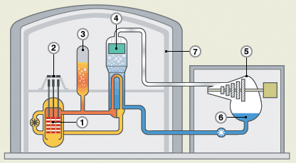
EPR
In this EPR diagram, the core is
shown in orange, the cooling circuit in light brown, the feed water is shown in blue,
the steam is colourless in one of the four steam generators, in the turbine and
its condenser.
AP1000
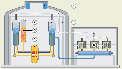
In this AP1000 diagram the core is
shown in red, the feed water to the two steam generators is in blue, while the
steam lines to the turbine are colourless.
ABWR
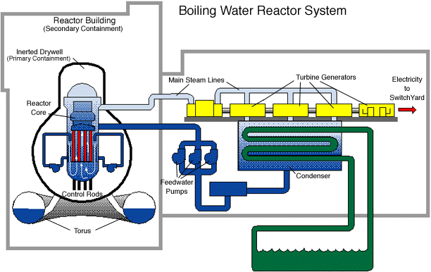
In this ABWR diagram the core is in
red, feed water in dark blue and the steam to the turbine is light blue. The
seawater to the turbine condenser is shown in green. A BWR has no steam
generators.
Reactor vessels
The critical part is the reactor
vessel, designed to contain the core and its control rods. The control rods are
moved up and down to regulate the amount of fission. In the EPR and the AP1000
they drop down to shut down the reactor, while in a BWR they are driven up
from the base to shut it down.
When operating, the reactor vessels
contain water at high pressure and temperature, ranging from 15.5 Mpa (2300 psi)
for the EPR; 10.8 Mpa (1566 psi) for the AP1000; to 7.1 Mpa (1060
psi) for the ABWR and from 327°C, to 320°C and to 288°C respectively. With lowering pressures the high
pressure hot water flashes to a steam/water mix and to steam.
The EPR and the AP1000 have steam
generators to separate the radioactive coolant from the steam to the turbine,
while the ABWR reactor vessel passes the steam from its upper part directly to
the turbine.
Core meltdowns
Core meltdowns occurred at Three
Mile Island 2 and Fukushima 1, 2 and 3
At TMI 2 the steam generator feed
pumps stopped working while the standby pumps valves were under maintenance. The
reactor was shutdown, but the residual decay heat raised the pressure, lifting
the relief valve, which stuck open, relieving the pressure.
At Fukushima, the earthquake
triggered the shutdown of all three working reactors. The control rods were applied and
the full heat reduced to the decay heat. The
tsunami caused the station blackout by disconnecting the station from the grid
and flooding the standby generators. So although some cooling was applied, it ceased after the
batteries ran out losing the controls.
The pressure rose in the reactor
vessels until the relief valves were opened manually by operators.
Hydrogen explosions followed the de-pressurisations. The explosion pressure was held by the containment at TMI 2;
at Fukushima the explosions caused catastrophic damage.
In all cases the control rods were
applied and the reactors shut down. Although only 7% of full power, falling
rapidly in hours, the decay heat was sufficient to create the explosions and
cause core meltdowns.
A near catastrophe
At Davis-Besse in the US in 2002,
boric acid leaking from a cracked control rod drive mechanism branch in the
reactor vessel head ate a large hole in the steel shell. The pressure was held
just by the stainless steel liner. Had the vessel ruptured at full power in
comparison with just the potency of the decay heat, the consequences are
unimaginable.
Hydrogen generation
A reactor vessel contains water at
high pressure and temperature. Reducing the pressure by venting turns the water
into steam, which it would be at that temperature but for the pressure.
The heat transfer from the fuel cans
to the water, without the forced circulation and with the water/steam mix turning to
steam, is poor. The surface of the fuel cans rises to produce an ion exchange
between the zirconium in the can and the steam leading to hydrogen and zirconium
oxide.
For the ion exchange reaction the
can surface rises to between 1000°C – 2,000°C so that the hydrogen leaves
the vent at more than its auto-ignition temperature of 585°C. Once the hydrogen/air mix is between 18.3% and 59% the hydrogen ignites and the mixture explodes.
At TMI 2 the containment held, while
at Fukushima 1 and 3 the service floors were destroyed.
De-pressurisation
For the emergency cooling water or
boric acid solution to enter the reactor vessel it has to be de-pressurised by
at least 2/3rds. As demonstrated at TMI 2 and Fukushima the venting causes the
internal high pressure hot water to flash to steam generating the hydrogen.
The steam and hydrogen leaving the
vent prevents the emergency water ingress.
The uncovered core melts, at TMI 2
the core melted partially, while at Fukushima the state of
the cores is unknown, but they have possibly already melted through the bottom of the
reactor vessels.
There were emergency core cooling
systems at Three Mile Island and Fukushima, but in all four events failed to prevent
the core meltdowns. The entry of the emergency cooling needs the prior de-pressurisation of the reactor vessel, which then causes the hydrogen
generation and the uncovering of the core. It can be concluded that ECCSs can’t work
HM Chief Nuclear Inspector's Fukushima Report Paragraphs 176/7 page 35
TEPCO concluded in the early hours of 12 March 2011 that there was a possibility that the PCV (pressure containment vessel) pressure had exceeded its maximum operating pressure and at 06:50 local time, the regulator ordered TEPCO to take measures to reduce the pressure in the PCV. To this end, TEPCO managed to manually open a motor operated valve in the PCV vent line to 25% at about 09:15 local time 12 March 2011. Despite high radiation levels they strove to open a second, air operated, valve in the subsequent hours. These attempts were successful because the PCV pressure had reduced by 14:30 local time.
At 15:36 local time an explosion, presumed to be an hydrogen explosion, occurred in the upper part of the reactor building. The roof, the outer wall of the operation floor and the waste processing building roof were destroyed. Radioactive material was released by the explosion, increasing the radiation dose in the surrounding area.
John Busby 10 August 2017